
On this page
When engineers design an ozone system, most early discussions focus on process performance: ozone dose, generator capacity, oxygen supply, cooling, mass transfer, contact time, and hydraulics. Those are essential design questions.
But eventually every part of the ozone system has to communicate with something else. A flow meter must tell the controller how much water is moving. The oxygen system must report whether feed gas is available. The chiller must indicate that cooling is healthy. An ambient ozone monitor may need to shut the system down. The plant SCADA system may need to start the ozone package, change a setpoint, monitor production, and receive alarms.
Those connections are handled through I/O, or inputs and outputs. They may appear as only a few pages in a submittal, but they define how the ozone system communicates, responds, protects itself, and integrates with the plant.
The I/O list is the engineering handshake between the ozone package and the facility around it.
What Is I/O?
I/O stands for input/output. In an industrial control system, inputs bring information into a controller. Outputs allow the controller to command equipment or communicate a condition to another system. The PLC uses these signals, together with programmed logic, to determine what is happening and what the ozone system should do next.
Four signal categories are commonly encountered in packaged ozone systems:
- Digital inputs (DI): discrete status signals received by the ozone PLC
- Digital outputs (DO): discrete commands or status signals sent by the ozone PLC
- Analog inputs (AI): continuously variable process measurements received by the ozone PLC
- Analog outputs (AO): continuously variable commands or retransmitted values sent by the ozone PLC
A modern system may also exchange a large amount of data through an industrial communications network rather than dedicating a physical wire to every signal. The engineering function is still the same: define what information is exchanged, who owns it, what it means, and what action follows from it.
Digital Inputs: What Is Happening?
A digital input represents a discrete condition. The controller sees one state or another: on or off, open or closed, running or stopped, normal or faulted, available or unavailable.
Examples in an ozone system may include:
- Emergency stop active
- Ambient ozone alarm
- Chiller common fault
- Oxygen system available or faulted
- Compressor running or faulted
- Booster pump running
- Off-gas destruct available
- Low cooling-water flow switch
- Valve open or closed confirmation
- Remote start request from plant SCADA
The important engineering question is not simply whether a signal exists. The project team must define what the signal does. Does it create an operator alarm? Does it block startup? Does it shut down ozone generation immediately? Does it allow a timed restart? These decisions belong in the control philosophy and I/O documentation.
Digital Outputs: What Should Happen?
A digital output is a discrete command or indication sent from the ozone controller. It may operate local equipment or provide a hardwired status back to the plant.
- Start or enable an oxygen generator
- Start a chiller or booster pump
- Enable ozone generation
- Open or close an actuated valve
- Energize an alarm beacon or horn
- Provide system running, ready, or common alarm status to plant controls
Digital outputs are often part of a sequence. The PLC may need to confirm cooling, feed gas, process flow, destruct availability, and other permissives before it issues an ozone-enable command. A single output therefore may represent the end of several engineering checks.
An I/O point is not just a wire. It represents an operating decision in the control philosophy.
Analog Inputs: How Much?
Analog inputs represent continuously variable process values. Instead of simply knowing whether flow exists, the PLC can know how much flow is present. Instead of knowing that pressure is acceptable, it can monitor the actual pressure and use that value for alarms, trends, or control.
Typical ozone-system analog inputs may include:
- Process-water flow
- Oxygen or feed-gas flow
- Feed-gas pressure
- Ozone concentration
- Dissolved ozone residual
- Oxidation-reduction potential (ORP)
- Cooling-water temperature or pressure
- Ambient ozone concentration
- Contact-system pressure or other process measurements
Common industrial analog signals include current and voltage signals such as 4-20 mA or 0-10 V, although the actual signal type must be defined by the project and equipment. The PLC scales the electrical signal into engineering units such as gpm, psi, degrees, ppm, or percent ozone by weight.
Analog Outputs: Controlling the Process
Analog outputs allow the controller to send a continuously variable command to another device. In an ozone system, an analog output might be used for a variable-frequency drive speed reference, a control-valve position command, or a process setpoint transferred to another controller.
The distinction between monitoring and control matters. An analog input might tell the ozone PLC that plant flow is 700 gpm. The PLC may then calculate the ozone requirement and adjust generator output. The measurement is the input. The resulting command is the control action.
This is the foundation of flow-paced and closed-loop ozone control.
From I/O to Control Logic
I/O only becomes useful when the control logic defines what to do with it. Ozone systems often contain three control concepts that should be clearly distinguished: permissives, interlocks, and alarms.
Three Different Functions
- Permissive: a condition that must be satisfied before equipment is allowed to start or continue a sequence.
- Interlock: a condition that forces or prevents an action to protect personnel, equipment, or process operation.
- Alarm: an indication that informs the operator of an abnormal or noteworthy condition; an alarm may or may not cause a shutdown.
For example, process-water flow may be a startup permissive. Loss of that flow during operation may become an interlock that disables ozone generation. The same event may also create an alarm and be transmitted to SCADA. One field measurement can therefore serve several different functions.
Ozone Safety Depends on Correct Interfaces
Ozone is a powerful oxidant, so control interfaces are part of the safety architecture. A well-engineered ozone package may use I/O to respond to conditions such as:
- Ambient ozone detected in the equipment area
- Loss of process-water flow
- Loss of cooling
- Feed-gas pressure or quality outside the acceptable range
- Off-gas destruct unavailable
- Emergency stop activated
- Generator, power-supply, or auxiliary equipment fault
The exact response must be project-specific. Some conditions require immediate shutdown. Others may block startup, create a warning, or allow an orderly sequence to stop. The critical point is that these responses should be engineered and documented before commissioning, not decided in the field under schedule pressure.
The I/O List Is an Engineering Deliverable
A good I/O list does more than identify tag names. It gives the owner, engineer, integrator, electrical contractor, and equipment manufacturer a common definition of each interface.
For each point, useful information may include:
- Tag or signal name
- Signal description
- DI, DO, AI, AO, or network data type
- Source device and destination controller
- Signal range and engineering units
- Normal and fail state
- Alarm, permissive, or interlock function
- Hardwired versus network communication
- Responsibility for field wiring and termination
- SCADA display, trend, alarm, or control requirement
This level of definition prevents a common project problem: both sides assume the other side is providing the same signal, or each side interprets the signal differently.
Who Owns the Signal?
Interface ownership should be established early. If the plant provides a process-flow value, the documents should identify whether the value arrives as a hardwired 4-20 mA signal, an Ethernet data tag, or some other interface. The same applies to remote start, ozone dose setpoint, common alarm, system ready, and other plant-level signals.
The questions sound simple, but they affect panel design, PLC programming, conduit, field wiring, network architecture, checkout, and schedule.
Engineers should define:
- Who generates the signal?
- Who provides the wiring or network connection?
- Where does the signal terminate?
- Which controller owns the logic?
- What happens if the signal is lost?
- How will the point be tested during startup?
Hardwired I/O Versus Network Communication
Traditional interfaces use individual conductors for each hardwired signal. Modern control systems may instead exchange many data points over industrial Ethernet or another communications protocol.
Network communication can reduce physical wiring and make additional diagnostic and process information available. EtherNet/IP, for example, is an industrial Ethernet protocol built on standard Ethernet and TCP/IP technologies with the Common Industrial Protocol. Modbus is also widely used to exchange process data between industrial control devices.
The choice between hardwired and networked signals is not purely a question of convenience. Project teams should consider reliability, owner standards, cybersecurity, maintainability, troubleshooting, required fail states, and whether selected critical shutdowns should remain hardwired.
More data does not automatically mean better integration. Every transmitted point still needs a defined purpose, owner, range, and response.
SCADA Integration Should Be Designed, Not Added Later
Plant SCADA typically needs more than a single running indication. Operators may need visibility into ozone production, concentration, flow, equipment status, alarms, setpoints, and operating mode. The owner may also want historical trending for troubleshooting and process optimization.
Useful SCADA data can include:
- Ozone generator output
- Ozone concentration
- Feed-gas flow and pressure
- Applied ozone dose or dose setpoint
- Process-water flow
- Dissolved ozone or ORP where used
- Generator, chiller, oxygen system, and pump status
- Active alarms and shutdown causes
- Local/remote and automatic/manual mode
- Runtime or maintenance information where required
The right list depends on the facility. A small stand-alone installation may need limited remote information. A municipal plant with centralized SCADA may expect detailed monitoring and selected remote control. Those expectations need to be captured during design.
Pinnacle Controls and Communication
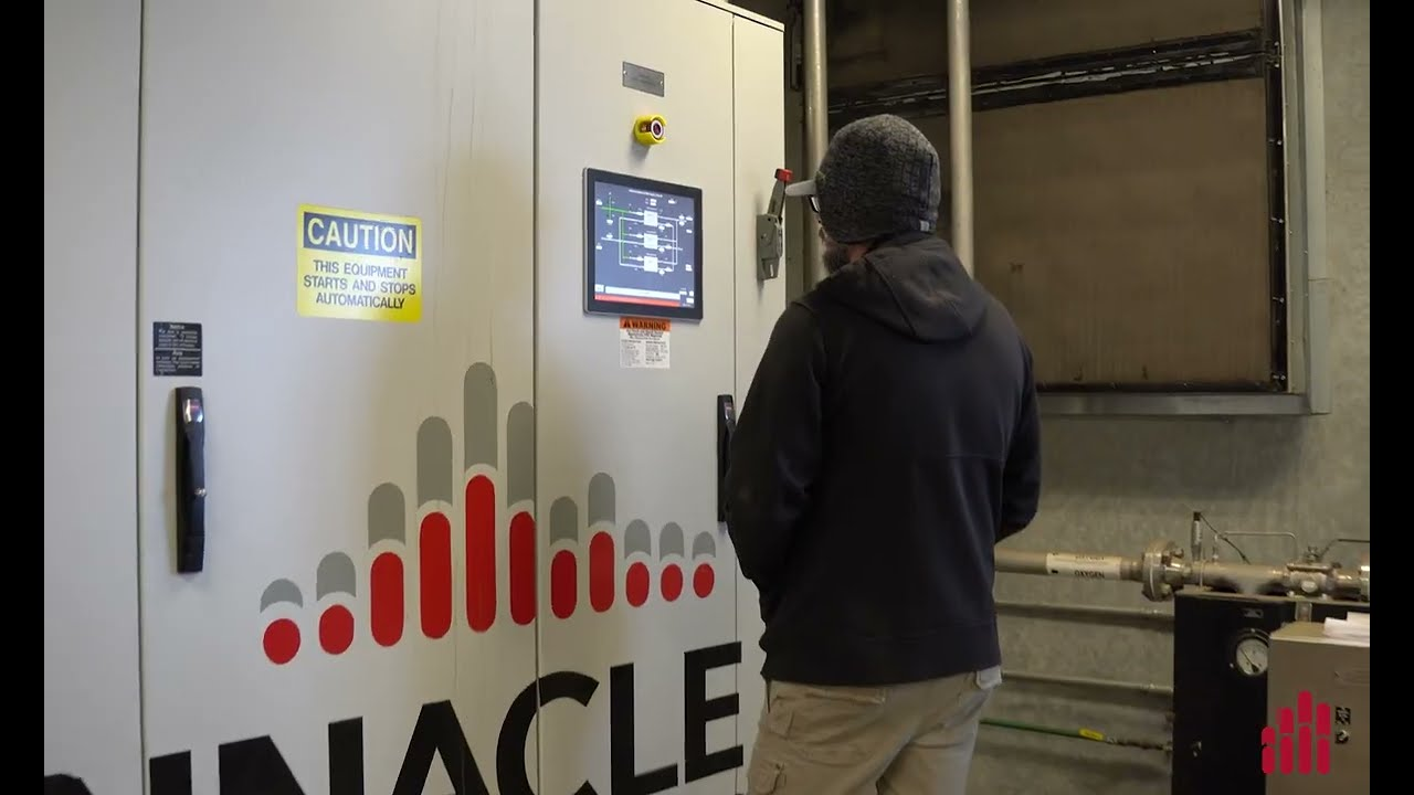
Pinnacle ozone systems are engineered with integrated PLC and HMI controls rather than treating controls as an afterthought. Published Peak technical specifications identify a Schneider Electric Modicon M251 PLC, a 15-inch Red Lion color touchscreen HMI, remote access, and an Ethernet/IP/webserver interface. Pinnacle also publishes automatic PID control routines using ORP or dissolved ozone, along with manual fixed-output modes.
The Peak 5X Plus integrated system is described as PLC + HMI controlled and SCADA-ready. These capabilities are valuable because an ozone system frequently has to coordinate the generator, oxygen supply, chiller, injection equipment, analyzers, safety devices, and plant control system as one operating package.
The technology provides the communication capability. Engineering determines how that capability should be applied to the specific plant.
Why I/O Problems Show Up During Startup
Many integration problems do not become obvious until commissioning because that is the first time all parties are connected at once. Common problems include:
- A 4-20 mA signal is scaled differently in two controllers
- A contact is normally open when the receiving logic expected normally closed
- The plant expects remote control but the ozone package was designed for monitoring only
- A signal exists in the PLC but was not mapped to the communications register or SCADA tag
- A critical permissive is missing from the control narrative
- Two systems use different names for the same operating state
- The fail-safe response to lost communication was never defined
These are rarely difficult problems to solve technically. The cost comes from solving them late, when contractors, programmers, operators, and commissioning personnel are already on site.
Factory Testing Should Include the Interfaces
A factory acceptance test should not verify only that the ozone generator starts and produces ozone. Where practical, the controls portion should also exercise the important interfaces and logic.
Testing may include:
- Simulated analog inputs at low, normal, and high values
- Digital permissive and interlock checks
- Alarm and shutdown verification
- Remote start/stop logic
- Setpoint range and scaling checks
- HMI alarm and status indications
- Network communication mapping
- SCADA point-list review or simulated data exchange where the plant system is available
The objective is to discover interface problems before equipment arrives at the site. A well-developed I/O list and sequence of operations make that testing much more efficient.
What Engineers Should Ask
When reviewing an ozone controls submittal, engineers should ask more than which PLC is being supplied. Important questions include:
- Is there a complete I/O list?
- Are hardwired and network points clearly distinguished?
- Are analog ranges and engineering units defined?
- Are permissives, interlocks, alarms, and shutdown responses documented?
- Who owns each plant-to-ozone interface?
- What happens if a critical signal or network connection is lost?
- Which points are available to plant SCADA?
- Which remote commands are permitted?
- Are naming, scaling, and fail states coordinated with the plant integrator?
- How will the interfaces be tested during FAT and startup?
These questions turn I/O from a wiring exercise into an engineering review of how the treatment system will actually operate.
The Pinnacle Engineering Perspective
At Pinnacle Ozone Solutions, controls engineering is part of complete ozone-system engineering. Ozone generation, oxygen supply, cooling, injection, instrumentation, safety systems, PLC logic, HMI operation, and plant communication all have to function together.
A strong I/O design supports:
- Predictable startup and shutdown sequences
- Clear safety interlocks
- Accurate process control
- Cleaner SCADA integration
- Faster factory and field testing
- Easier troubleshooting
- Better long-term documentation and serviceability
The value is not the number of I/O points. The value is knowing exactly what each point means and how it contributes to safe, reliable ozone treatment.
Conclusion
An ozone system is not complete when the generator, chiller, oxygen system, and injection equipment are simply installed next to each other. They become a system when the controls connect those pieces into a coordinated process.
I/O is the language that makes that coordination possible.
Well-engineered inputs and outputs allow the PLC to understand process conditions, enforce permissives and interlocks, control equipment, communicate with operators, and integrate with plant SCADA. Poorly defined interfaces create confusion exactly where projects can least afford it: during startup and operation.
For engineers, contractors, operators, and equipment manufacturers, the best time to solve I/O questions is during design. By commissioning, the objective should be verification, not discovery.
Good controls engineering makes the ozone system easier to start, easier to operate, easier to troubleshoot, and easier to integrate for the life of the equipment.
Technical Source Notes
- Pinnacle Ozone Solutions, Peak Technical Specifications. Published controls information identifies a Schneider Electric Modicon M251 PLC controller, 15-inch Red Lion color touchscreen HMI, remote access, Ethernet/IP/webserver interface, and automatic PID control routines using ORP or dissolved ozone.
- Pinnacle Ozone Solutions, Peak 5X Plus. Pinnacle describes the integrated system as using PLC + HMI controls for automation and monitoring and as SCADA-ready.
- Rockwell Automation, POINT I/O product documentation. Rockwell identifies digital, analog, specialty, and safety-rated I/O as industrial I/O module categories, consistent with the signal classifications discussed in this article.
- ODVA, EtherNet/IP. ODVA defines EtherNet/IP as an industrial Ethernet protocol that combines standard Ethernet and TCP/IP technologies with the Common Industrial Protocol (CIP).
- Modbus Organization, Introduction to Modbus and Protocol Specifications. Modbus is an application protocol designed for exchanging process data between industrial control devices. Project-specific implementation, physical network, data mapping, and security still require engineering definition.
Prepared as a technical education article for Pinnacle Ozone Solutions. Final I/O architecture, signal types, safety logic, communications protocols, fail states, SCADA integration, cybersecurity requirements, and control responses should be defined for the specific project, owner standards, equipment configuration, and applicable codes.
